O.K., everybody, here you go. Any other questions, post away or send me a pm or e-mail
CBX OKI Swap
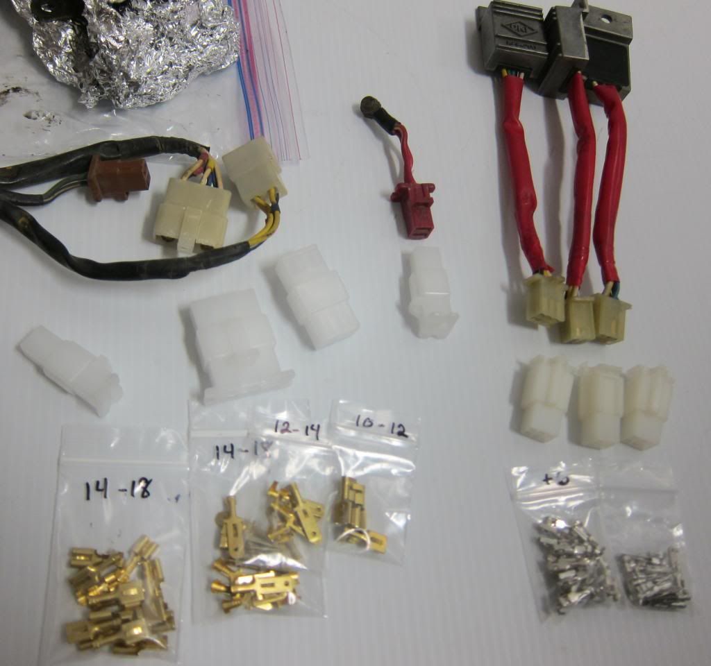
You want to replace the early model igniters (OKIs) with the late model (red shrink wrap) igniters.


You should consider relocating the OKIs from under to above the battery case. The Prolink rear inner fender provisions to hold the wire ends will really help.


You will have to make a small wire harness for the connection. Make sure it is long enough to connect to the three original early model connectors – a 6-pole connector for the 3 blue and 3 white wires, a 4-pole connector for 3 yellow and 1 black/white wire and a 2-pole connector for a black/white and green wire.

The connection is a little complicated as the number of wires doesn’t match – the early CBX OKI set has 12 wires and the 3 separate OKIs from the late model have a total of 15 wires.


It would be extremely helpful to have a wiring diagram for both models in order to compare and fully understand the wire routing.
The blue, white and yellow wires must be in a specific location as they correspond with the ignition pick-up and the respective coils for cylinders 1-6, 2-5 and 3-4.
For ease of description, the OKIs and their connectors are identified with numbers: 1, 2 and 3. No1 corresponds with pick-up and coil 3-4, No2 corresponds with 2-5 and No 3 corresponds with 1-6.
Let’s start with the blue and white wires, 6-pole connector.
OKI No1 blue and white wires connect to the pink wires in the original connector
OKI No2 blue and white wires connect to the yellow wires in the original connector
OKI No3 blue and white wires connect to the blue wires in the original connector
Make sure the white wires connect to the wires in the connector with the small white tubes.
The yellow wires, 4-pole connector
OKI No1 yellow wire connects to the yellow wire with the red tube
OKI No2 yellow wire connects to the yellow wire with no tube
OKI No3 yellow wire connects to the yellow wire with the blue tube
The fourth pole for the black and white wire bridges to the black and white wire connection of the 2-pole connector
The black/white and green wires, 2-pole connector.
All 3 green wires connect to the one green wire connection in the 2-pole connector
All 3 black and white wires connect to the black/white connection in the 2-pole connector
A bridge needs to be made from the black/white wires to the fourth pole of the 4 pole connector (above)

Plug in!